DIY Coil Winder Project
In my continued effort to waste time not working on automotive projects I decided I was going to make my own version of an MSD Ignition. I has seen a schematic for a CDI Multi-spark ignition system that I could make (and modify) so in figuring out what I would need it seemed like I was going to have to wind the transformer (coil) by hand. After poking around eBay and other places on the web you could buy a Chinese-eium based manual or electric winder. Manual winders looked really sketchy and the electric winders were a lot of $$ and mostly ran on 220 volts. Some other CNC and higher end winder were really out of budget. Then a light bulb (Incandescent and somewhat dim) lit over my head. I have almost all the parts, let's make a winder to wind the coils (a recursive project).
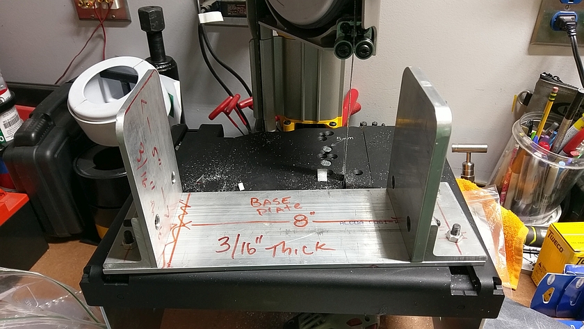
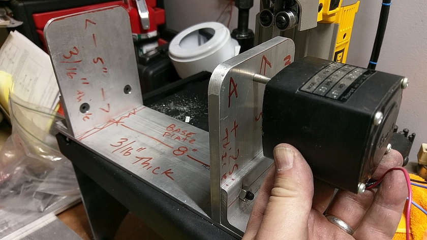
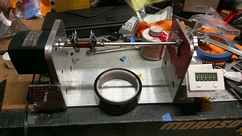
So in all it's glory here is my over build winder. It's mainly for the ETD-29 and ETD-39 cores but you can modify the holders to mount most anything that will spin.
Note that this is not a high speed, but a slow speed easy to use model.
Parts
All sorts of scrap metal and angles. I used mostly all aluminum that I had left over. Much of it was pretty conventional, but a couple of pieces were pretty thick, but that could also be avoided.
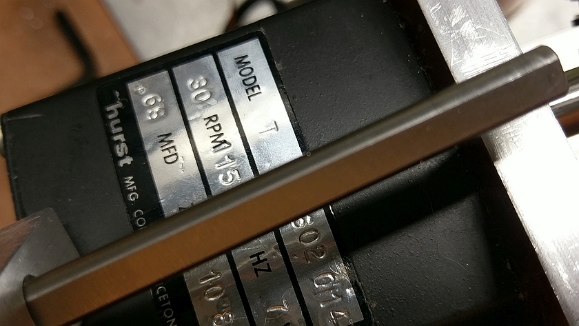
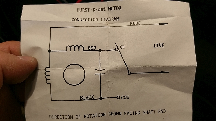
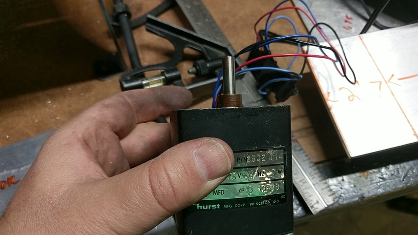
Motor - Hurst Series T 30 RPM gear motor. You can find these on eBay used in the $20 range. The key here is that it's a slow speed gear motor and will have plenty of torque and not stall out. You and find these all over the RPM range, I had a 30 and a 60 rpm and went with the slower. These do require a capacitor to start so if a used motor you will need to get the proper size to make it all work. The motors are also reversible which is a nice feature. Note this motor has a 1/4" 'D' shaft which is nice and mounting is easy for this motor.
Switch and wiring if desired to have on/off etc.
Nuts and bolts in various size. Mostly from the parts pin, used some fancy counter sink fasteners but not at all needed.
Digital counter (About 15 bucks from Amazon) comes with all you need including battery and magnet!
1/4" Shaft, couplers and bearings were picked up from a company called (Servo City). All parts were for 1/4" drive. They have both round shaft and 'D' shaped shaft. I picked up one of each in 12" length. The 'D' shape shaft is better as you don't have to crank things down to make it keep from spinning. A few other bits from them. Some was not really needed but made for a better build.
Tools needed
Saw for metal
Wire Cutters/Strippers
Screw Drivers
Hex Wrenches
Dychem Red (I used this because it smells good)
etc.
Scroll down (LOTS OF PICTURES)
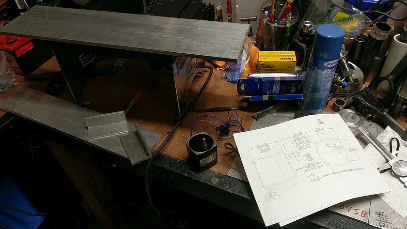
Pile of parts
Here is what I started with (well mostly). I had a bunch of 4" wide plate, some in 3/16" and some in 3/8". Then toss in a bunch of nice thick angle and I had enough to make something. The dimensions I came up with were pretty arbitrary and make them to fit your material. The coils are pretty small that I was going to work with so picked a size that worked for the material I had. Some parts as mentioned I did have to buy, like the digital counter and a few bit's of hardware from Servo City.
Chopping base on Dewalt Bandsaw
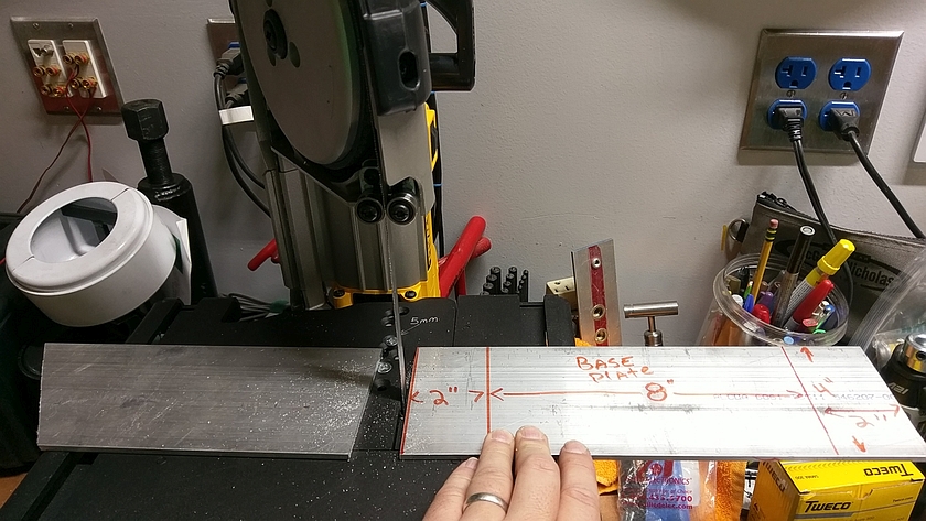
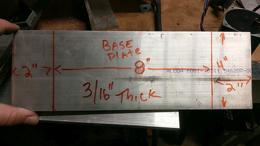
Measured up some coarse dimension and then sliced the metal up into a 12"x4" length of 3/16" Aluminum. Note accurate Sharpie (tm) markings.
Side Plates
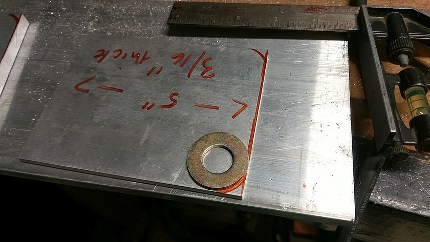
The Hurst gear motors typically have a bearing that sticks out (top photo) about 1/4". I had some 3/8" plate for that side so I didn't have to space off the motor to make it not stick out into the winding area it was made 5"x4"x3/8"
. It really didn't matter but I had some scrap so I used the thicker for the motor side (Just visible upper left corner). The other side plate was made of 5"x4"x3/16". Using ADVANCED machining techniques I radiused the edges to keep from getting cut by the edges.
Squaring Up and Drilling
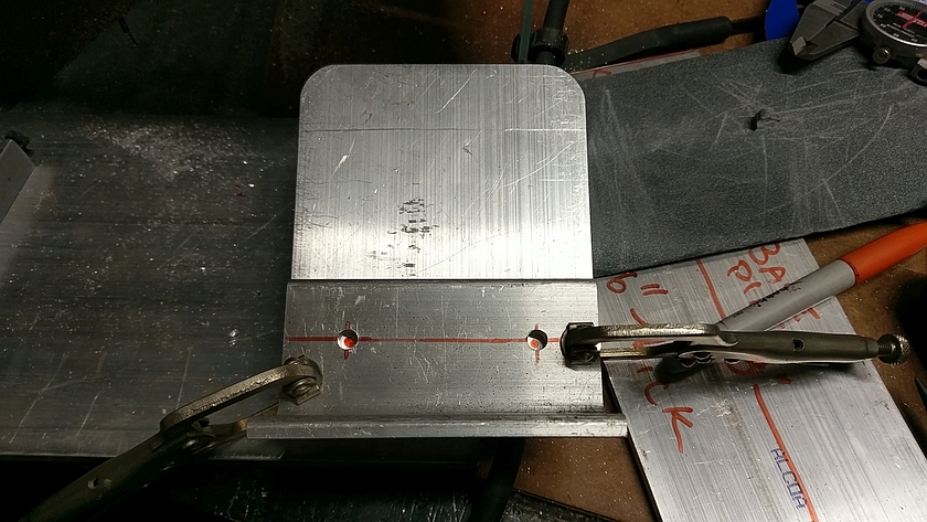
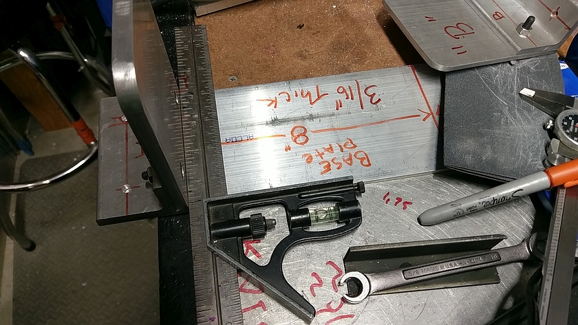
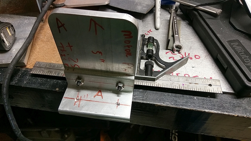
For both sides I squared them up to the brackets and set them flush on the top of the base plate. Then marked the holes. Note that their will be some play in the holes (drilling a bit larger then the 1/4" fastener) so things can be tweaked to make perfect. Welding vice grips are a nice helper here.
Marking and Mounting Side Plates
The most square line I have is the side of the bottom plate so I use that to try to get things square before drilling the angle brackets. This is important since you want both the motor plate and the back bearing plate to be parallel to each other. Using a small square here helps. Again drilling a touch larger hole in the brackets helps allow for some adjustments.
Motor Mounting
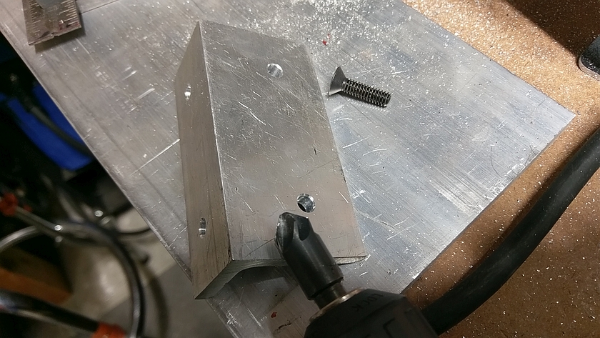
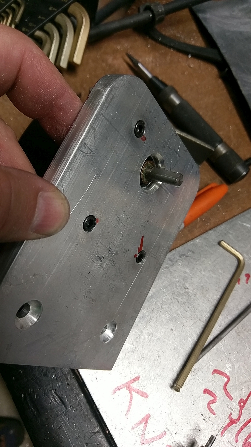
After the side plates are set up, take off the motor plate and make a mounting patter for the motor you used. The Hurst motors have a nice layout you can get from the HURST site here's one for the Model T Gear Motor. Do one for your model of motor. When setting up your motor take into consideration the height of the output shaft and how it will affect how the coil might hit the bottom plate. I recessed the mounting bolts to the motor just for fun, but not really necessary.
Taking it for a Spin
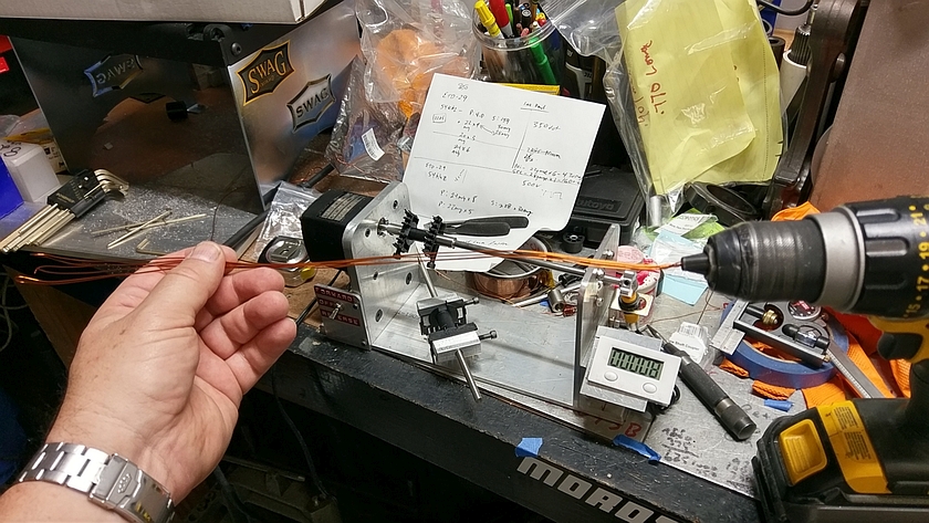
After some hacking around I took a couple of shots with the winder. The foot switch makes it really nice, no fumbling around with the switch, just set the direction and step on the gas!
The project was made in my garage without any thing more complicated then a small table band saw. Hack saw, jig saw would have worked just as well. Bring a drill and a few other bits and this is an easy project to make. Metal cost might be the only issue if you don't have a bunch of scrap laying around, I would expect about $40 or so for that, add in another $60 or so for the motor and rest of the parts and you are good to go. Plenty of places to save as well, skip the counter, get a used motor, no bearing, etc.
I really liked making this project, hope my coil winding comes out as well...
Happy Motoring and GET them projects done!
Bearing Mounting
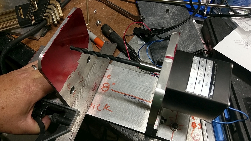
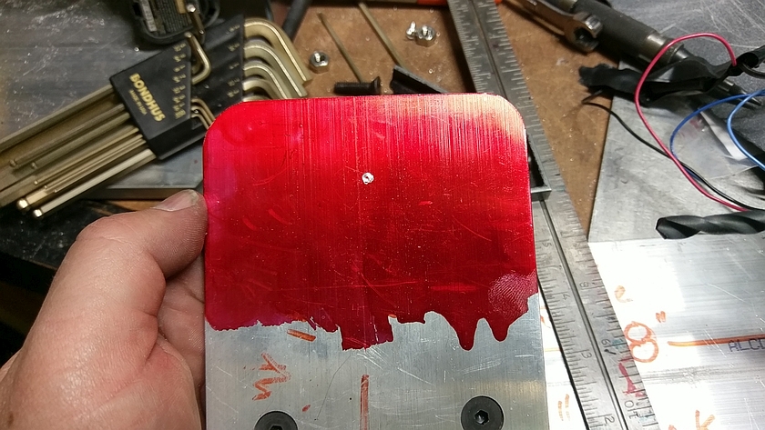
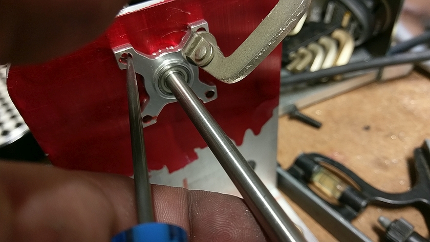
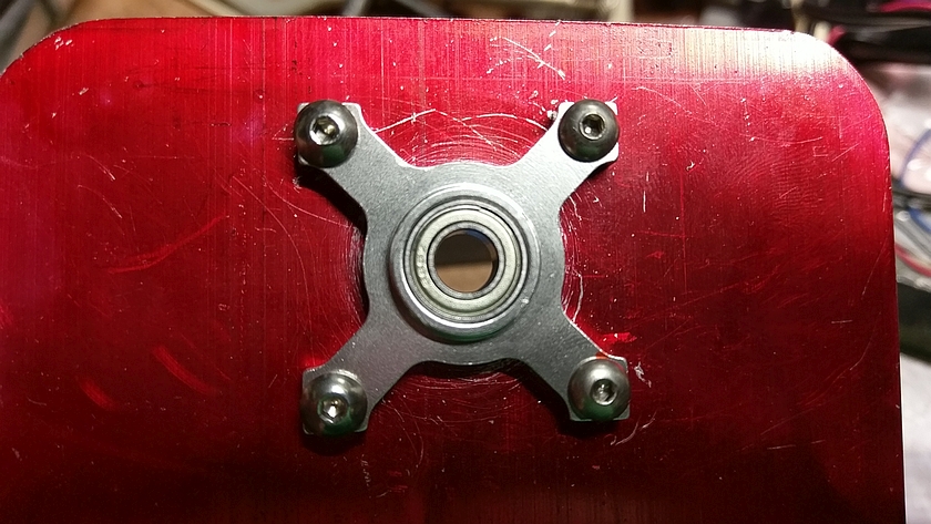
I thought about this for a while and since things are not super accurate between both side plates I thought of an easy way to mark for the bearing. I used one of the 1/4" couplers and stuffed the largest drill I could find that would fit and plugged in the motor (with the capacitor) and squared up the plate to be drilled. Moved it until the drill marked up the red dychem and I was hoping I was pretty close... it actually was for a change!
The last step was to use the same drill bit to drill a hole where the marking was. This was a tight fit for the 1/4" shaft but then provided a way to mark the location for the bearing. If you didn't have a bearing like I used, I think just riding it on the thick aluminum would be OK with a drop of oil.
Coil Winder Almost Done
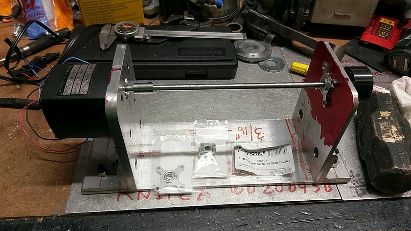
Almost done with the metal work. Still a bit more to do but you can see how it's taking shape. Some spare parts from Servo City on the bottom. I'm also using the round shaft, as mentioned I also have a 'D' shaped shaft. Once other nice thing about the 1/4" shaft size is that you can use a knob with a set screw from old electronic projects to help twist or pull out the shaft, which you will have to do.
Get the Shaft
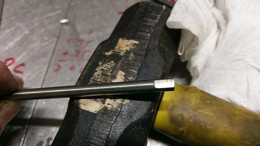
If you use the 'D' shaped shaft you are in good shape... get it. If you are using the round 1/4" shaft you might want to file a small flat where it goes into the coupler of the motor. If you don't the set screws will mark up the round shaft and it will be a pain to pull out of the bearing. It also make it easy to lock the shaft in with no spinning.
Switch Wiring
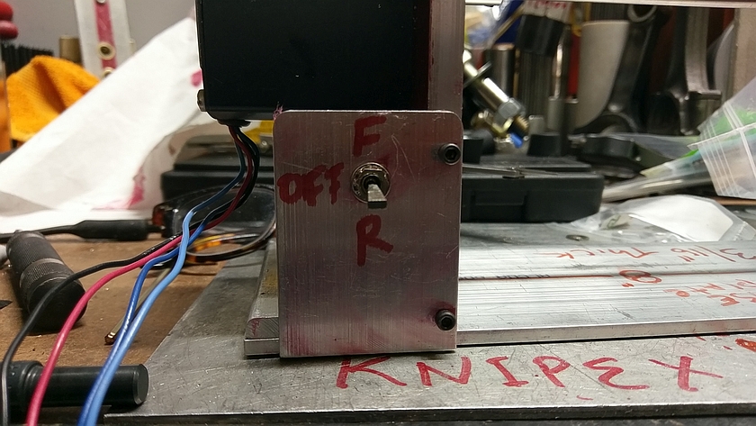
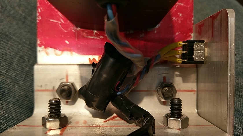
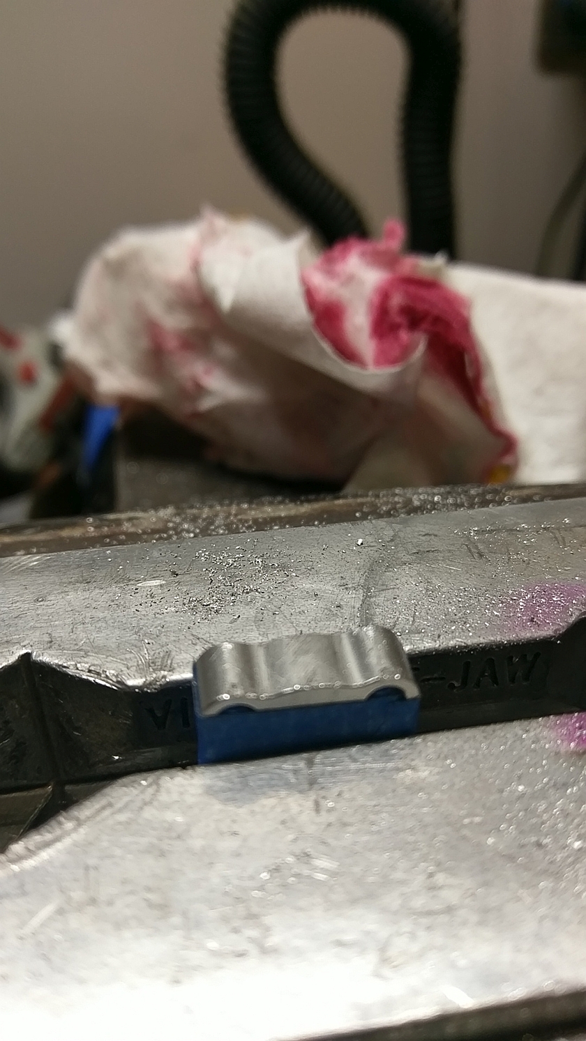
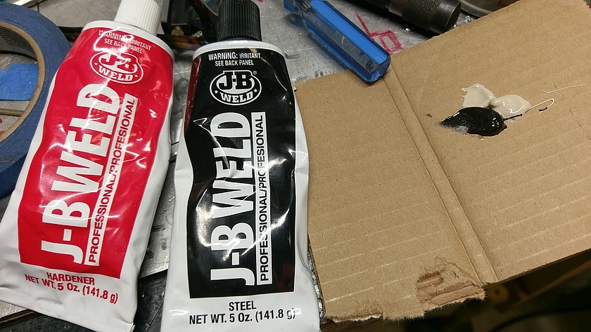
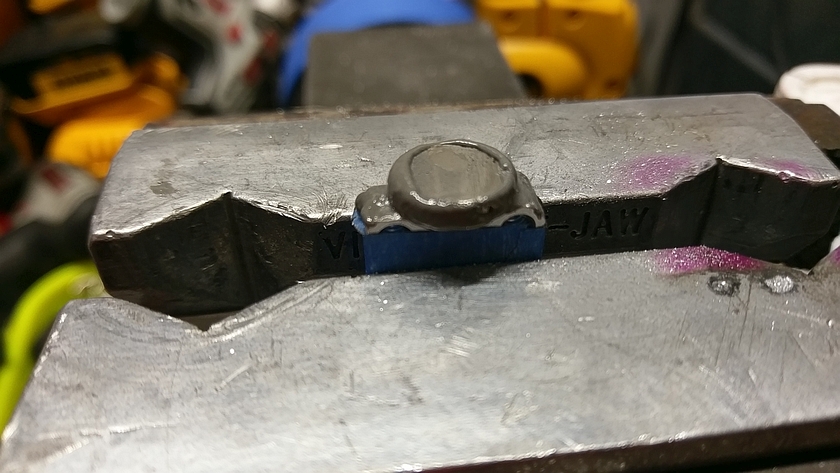
Using what I had I found a DPDT switch, you only need a SPDT switch for forward and reverse. I soldered up the capacitor and switch using heat shrink tubing over all connections and then wrapped up the capacitor with some electrical tape just for extra protection. Not show is the strain relief I made for the cord that keeps things from pulling out in the event of a mishap.
Setting up the Turns Counter
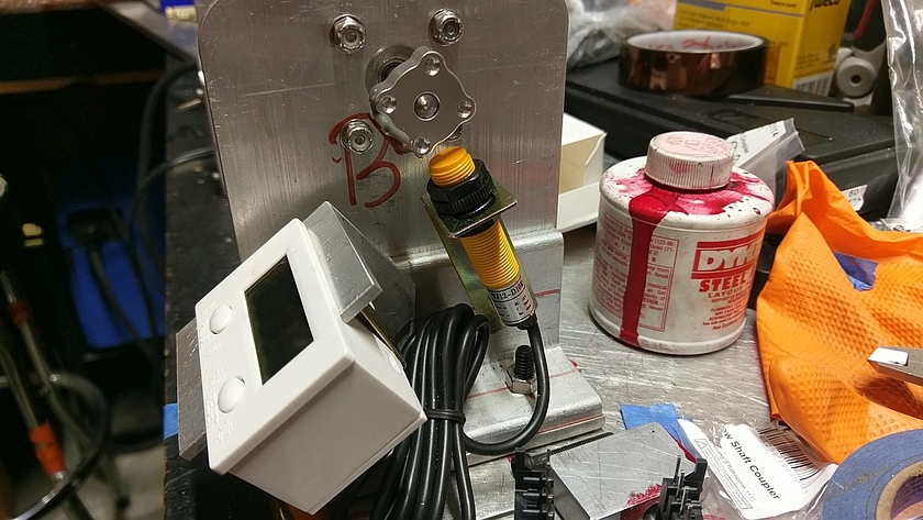
I using the counter I picked up from Amazon, I used a piece of Angle and cut out a slot for it, and just used the existing bolt to hold it. The aluminum angle size wasn't quite long enough to hold it all in, but still plenty good. The pick up coil for the counter was mounted to one of the bolts on the side as well. The pick up needs to be positions where the spinning magnet goes, and doesn't need to be super close, just close enough to register for each turn. One problem is if you don't have something to mount it on, and just tape it to the shaft, it may count 2 turns unless you adjust the pickup a bit further away, it's pretty sensitive.
Coil Form Holders
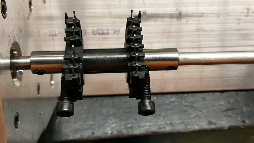
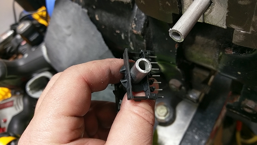
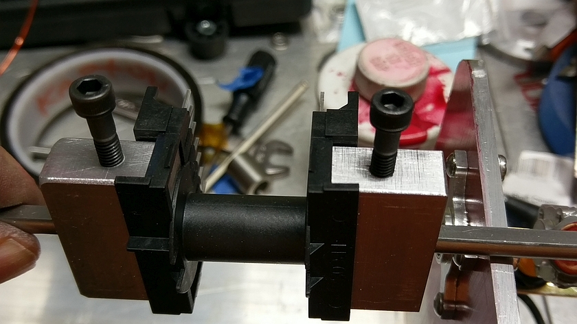
For the EDT29 I used some longer allen (hex head) bolts in the 1/4" couplers to keep things from twisting. I also found a piece of small tubing that fit jut inside the EDT29 coil former. It was a bit loose on the 1/4" shaft, so I added a little blue tape and it seems to be centered and locked in.
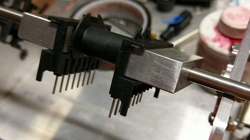
The EDT39 coil former was big enough to use some 1/2" scrap that I cut to fit on the inside of the form. It's centered and bolts to the shaft with a hex head bolt.
Both seem to be pretty solid! For the 'D' shaped shaft it's nice and easy to use since the hex head bolts can be just thumb tight and they don't spin. No crazy load on the coil forms either.
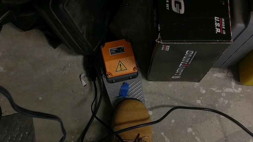
The DIY Foot Switch is Key!
For the portable band saw table I have, I needed a foot switch to operate it. So as part of yet another project I made up a DIY Foot Pedal Switch. Seemed like it would also work perfectly for the coil winder. Allows both hands to be free and a quick stop if something gets cross wound. You can pick these up on Amazon as well.


