Sunbeam Tiger Brake Bracket and Upgrade
This page is to show how I made a couple of Brake Caliper mounts for the Sunbeam Tiger aftermarket suspension. The original used
Wilwood Dynalite 4 piston calipers, but being someone who can't leave well enough alone I had to change them to use the much
larger Superlite 6 Piston calipers. The main reason is that I could! But one thing that I have never liked about the Dynalite calipers is that the pad area is very small. I would never use them on the front brakes on heaver car than the Tiger. I think they would have worked OK with a good pad, but OK is not good enough. My Mustang uses the 6 piston Superlite calipers and they work very well. Also figured would be good to have more of the same shared parts across both platforms. Note this bracket could work on any Mustang II spindle.
The modifications start with the NEW Tiger front end. This subassembly was made and included Mustang II / Pinto spindles. They are a bit odd to make a bracket for as you can see the bolts that fasten the bracket are pointing 90 degrees apart. Wilwood makes a kit for the Mustang II spindles that looked like it could work, but when trying the parts the offsets would not work. The Tiger has a very narrow wheel base and it needs a lot of stuff tightly packed towards the spindle. This doesn't leave much room for wide calipers, thick rotors, etc. Then their is the problem of rim fitment as well. The target was for 15" rims.
This was a complex project, some of the issues were to get a very large caliper on a thick rotor in a very narrow space. Fortunately Wilwood has a very nice selection of parts if you can first find the right catalogs with the specs. The upgraded Tiger suspension came with 5 Lug Mustang 2 rotors with short pressed in studs. I first though I would keep the hubs and modified rotors, but after purchasing the imported parts for modification I quickly found that they were so poorly machined that they had to be replaced. I first upgraded the iron hubs to the Wilwood billet hubs with the correct offset. These are lighter and I'll bet stronger than the import crap. The aftermarket Mustang II spindles were also a bit suspect (poor accuracy) and I didn't find that Wilwood made some better replacement until after the bracket was done. After that it was a lot of measuring and sheets of paper to find parts that would yield the correct offset of the rotor and finally the caliper offset to that. Once that was all complete I made a simple bracket with Design CAD 2D and printed 1:1 then hit the Miller Plasma Cutter, and a lot of clean up grinding. Looked very good...Until the FAIL. Attempt 2 was better as I cut a fiberboard template to help guide the plasma cutter. Success... Much better part and fitment looked good. The part was designed to support drilling for 11.75" or 12.19" rotor diameter. The later was what I was shooting for but in my test fitment I forgot to change the the larger rotor and marked holes for the smaller. OOPS, but likely a better fit for 15" rims. Below are pictures and a few comments on some of the steps.
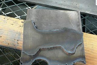
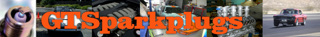
Brake Bracket Raw
Cut from 1/2" cold rolled steel. The metal was purchased from OnLine Metals. I used the old bracket and a Wilwood bracket to get a pattern that looked like it might work. Then did some CAD work. Printed a paper template and traced that onto the metal plate. Set up the Miller Spectrum 625 Plasma cutter do the hard work. As you can see I'm not a good free hand cutter but will be good enough once I get the grinder on it.
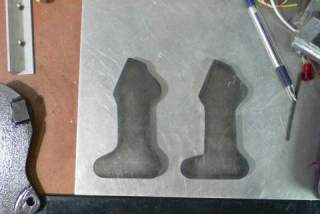
Pair of Raw Brake Brackets
Both brackets are now cut. Note the accuracy and repeatability of the free hand work (Read this as sarcastic). I could have used 3/8" material but figured the 1/2" would provide a bit more material for the threads on the calipers mounts, and would have no issues in the rigidity area.
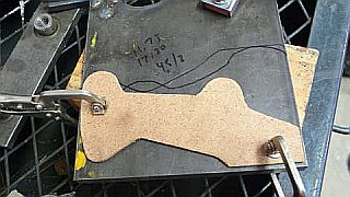
Bracket and CAD Template
The clean bracket after some masterful angle grinder work. This took about an hour for clean up of both brackets. It was a loud and messy task done outside. The paper template was the original pattern used before plasma cutting. The pattern was made for the 12.19" rotor, but I will not drill those holes until I verify the rims will go over the caliper and it will clear the rim face. If I have to I'll move the holes down and trim the bracket for the 11.75" rotor, that is if I have to...
New Template Pattern
This time I got smarter. Since I'm JOJO the plasma cutter boy I decided to make a melamine template out of some thin material. I did the same CAD paper print, then taped to the melamine and cut the shape with an Xacto knife. The material was thin about 1/8" as I recall. Should be easy work to get the part cut, no CNC machine but better than freehand. The pattern worked well, and the second set came out with less grinding required.
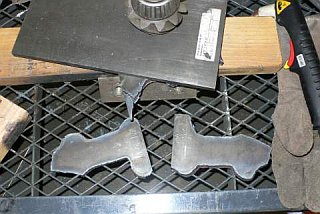
Clean Cut Brackets
After the dirty and noisy angle grinder work, I hit these on the vertical belt sander and made them pretty. These still need to have the block cut out for the top mounting pad and the tapped holes for the mounting. The caliper mounts are the right most bumps, the bottom left bump is where it bolts flat to the bottom of the Mustang II spindle. The angled flat at the top is where a boss will be welded to mount to the top of the spindle. If you look picture far left you can see how it looks on the other spindle that was made for the Dynalites.
Clean Notched Brake Brackets
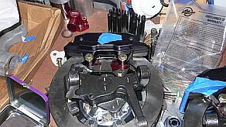
The Shots above are how the bracket goes together. Some additional The next step will be to make the matching one for the other side and then tack weld them into position once the proper offset is set. For my application with the specific brake hat and
1.25" thick rotor and a 0.5" thick mounting plate I will need approx. 0.147" Spacer on the bottom, the top will just slide along and hopefully still be parallel to the rotor face. These brackets would need modifications to work with 11.75" rotors as the brake mounting lugs would get in the way of the upper flange, so no reason at this point not to make them for the 12.19" rotors. From the look of the Bogart rims that were made for another Tiger, it looks like not only will the larger rotor and caliper will fit. It will be tight!
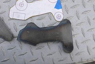
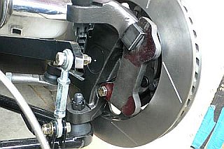
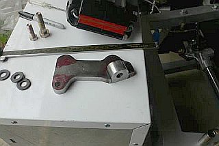
Bracket Test Fitment
This is how the bracket fits the spindle and how close it is to the brake rotor. It's a bit tricky dimensionally to make it work, but it finally all came together. NOTE : The slotted 12.19" Rotors. You will need to know that the 11.75" ones I have are NOT slotted. Remember this as you read on...
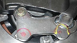
Brake Bracket FAIL
I forgot to take into account the bead from the weld. The yellow paint line shows the problem. My options were to grind the weld, or the brake or make a new bracket. I opted for the latter approach.
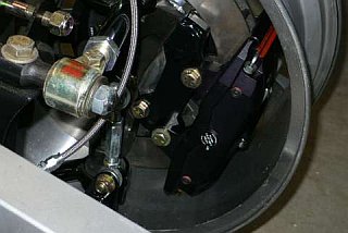
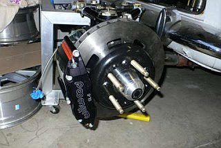
Mock Fitments Again
I skipped a few steps (you have the idea) and finally did some ugly welding. TIP - MAKE SURE YOUR MASK IS NOT SET TOO DARK! Well not yet the fail but a close one. If you had a sharp eye you might have noticed that these rotors don't have slots in them (remember I told you). HMM, I noticed that too and then let out a yell the could be heard around the world. In the design of the new pattern it was made to be able to support EITHER 12.19" or 11.75" rotors with some cutting of the mounting ears. When verifying this I checked with the 12.19" rotor than the 11.17". Guess what it looked good. So now back to work. Well after careful grinding and fitting I found that it looked ready for welding. After hitting it with the Millermatic MIG I started to look at the smaller non-slotted rotor. And realized I never put back the 12.19" to get the correct fitment. Oh well I guess I could whip up another set of brackets, but I don't have the mental capacity to do so, so now it's 11.75" rotors instead of the biger 12.19" This might be a blessing in disguise as these should really ensure 15" wheels will work.
Notice the nice Wilwood light weight brake hats, longer studs and mounted 6 Piston Superlite caliper!
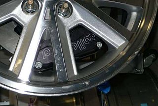
Checking Rim Fitment
After all this I tossed on a 2000 Mustang 16" wheel just to see what sort of clearence issues I might have. Suprisingly about the only issue was the center pilot hole on the rim was too small. The late model rims offset was way off but a spacer was added and it all bolted up and look great. I think their was over 1.5" of space between the top of the caliper and the rim. So should be OK on a 15"
Checking Rim Fitment
Although hard to tell from the picture the caliper has plenty of clearence from the back face of the rim as well as the inner diameter.
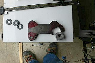
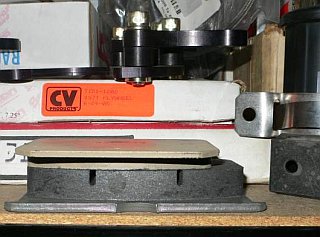
Dynalite vs. Superlite Pads
Here is the main reason why you should not use Dynalite's on heaver cars or extreme use situations. The amount of pad on the rotor with the Superlite pad is dramatically increased, but not only that look at the thickness of the pads! I have a vested stock of Superlite pads on the Mustang and again nice to have same parts being used on several cars, this will include the Mustang, Tiger and the RCR GT40. Don't get me wrong the Dynalite is a great caliper, but for heavy duty use, go with the Superlite and keep the Dynalite on the rear of the car.