Auxiliary Fuel Injector and Ignition Driver


This was a project that I did a long while back while working with a few folks on the EFI332 project. I made a few prototype parts for the project, this was one that was useful and something that could be used as a primary or auxiliary injector driver. The circuit is pretty simple, almost from the LM1949 Data sheet, The LM1949 was a National Semiconductor part, and not later I think sold off to Texas Instruments. The LM1949 is a PEAK AND HOLD driver that can drive saturated (high impedance) injectors as well as low impedance peak and hold style. It also can be used to drive IGBT's and other drivers with a bit of tweaking. This makes it good for solenoids, ignition coils, and other related devices. This can be driven by most anything that can drive a low powered LED.

Parts listing and notes at the bottom of the page.


Download the Texas Instruments LM1949 Datasheet (Rev. C) HERE
Download the PDF of the full schematic HERE
Fuel Injector and Ignition Driver

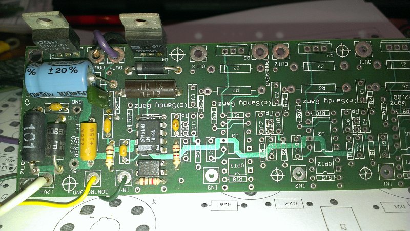
Voltage Regulator and Injector Drive


This is a shot of the power supply section and one channel stuffed for Injector drive.

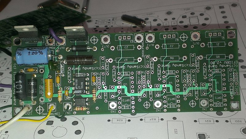
Top Layer of the Board


Another shot a bit further back. Note geneouse trace width for LM1949 Power Buss.

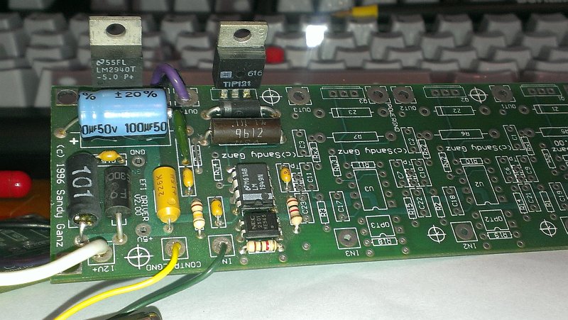
Injector Jumpers and Parts Population


The board was designed to support injectors and ignition coils depending on the parts used. Some parts are jumpered some are left out. The document at the bottom of the page tells what to do!

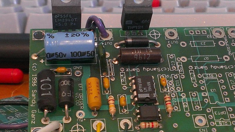
Close up of the LM1949


Just a bit closer shot of the board, the far left part is the choke, then the TVS next to that. The small 4 pin part below the LM1949 is an opto-isolator which is nice to keep your expensive CPU safe when someone blows or gets careless with an HT lead.

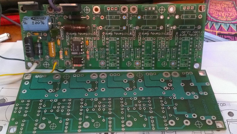
Bottom Layer of the Driver Board


These boards were done with 2 oz copper for additional current capability, I think the one thing I might change is add tick more spacing between the traces on the output transistor as it's a bit close for the 400v clamp that an IGBT has.
GTSparkplugs Header
Click for Contact Page Click for Contact Page

Auxiliary Driver Parts Listing and Notes


EFI DRIVER v2.00 Parts and Notes

Part  Used  Part Type               Designators                               
1     4     .05 3W IGN (.1 3W INJ)      R5 R6 R7 R8
2     4     0.001uF 400v or >           C1 C2 C3 C4
3     4     0.1uF                       C9 C10 C11 C12
4     1     0.1uF 50V                   C15
5     8     0.0022uF                    C5 C6 C7 C8 C20 C21 C22 C23
6     1     1.5KE30CAC                  TVS1
7     8     1k                          R13 R14 R15 R16 R17 R18 R19 R20
8     1     22uF 10V (tant)             C13
9     4     83k                         R9 R10 R11 R12
10    4     100k                        R1 R2 R3 R4
11    1     100uH 1amp                  L1
12    1     220uF 50v                   C14 (Supports Axial or Radial)
13    4     HGTP14N40F3VL (INJ TIP121)  Q1 Q2 Q3 Q4
14    4     LM1949                      U1 U2 U3 U4
15    1     LM2940-5                    U5
16    4     PS25010-1                   OPT1 OPT2 OPT3 OPT4
17    4     OPEN (INJ 0.033uf for Hold) C16 C17 C18 C19
18    4     OPEN (INJ 1N5364)           Z1 Z2 Z3 Z4 (1N5364 33 volt 5 watt) OR TVS
19    8     RES                         Rx1 Rx2 Rx3 Rx4 Ry1 Ry2 Ry3 Ry4 (See Below)
Highlighted Designators indicate changes between Ignition and Injector driver parts

This is the Quad driver sub-board. It currently is configured for Ignition. Minor component changes will result in the Injector driver with no layout changes. Rx and Ry determine the hold current. For 4 Amp Peak, 1 Hold (Injectors), use Rx=0, Ry=Open, Sense resistor 0.1ohm.  For Ignition, 8 amp, use Rx=100 Ry=33, Sense resistor of 0.05 ohm. C16, C17, C18, C19 Determine Peak Hold Delay, If open, no peak hold function. 0.033uf yields 3 ms hold. When using as ignition drivers, the peak hold function is not used, so leave C16-C19 open. If using TIP121 (or better) for injectors, remove C20, C21, C22, C23, change R9, R10, R11, R12 to 0 ohm jumpers, C5, C6, C7, C8 to 0.01uF. Add clamp zener 1-4 for injector drivers only. If using the IGBT for injectors, leave C20, C21, C22, C23, as they control some small output oscillations, I think they can be removed when driving ignition coils, but no harm will be had if they are left in.

   
Most parts are purchased from digi-key or mouser (except for the LM1949, IGBT). Z1-Z4 uses 1N5364 for injectors or can use a TVS of similar ratings. The TVS will be much more costly however. All resistors are 1/4 watt unless noted. Most small caps are axial ceramic Z5U or X7R and of 50V ratings. TP, Test Points, are for your pleasure... Also and extra component pad was added at the last minutes near R17-R20 for a noise cap if desired. Most of the power supply parts are non-critical. If you are running of a clean regulated 5v supply, it doesn't need to be stuffed. Pads exist for direct 5v connection, and are labeled. The pads can also be used to power another board if needed (check power dissipation on LM2940). Also if you don't want to use the opto-isolators, just drive the input of the LM1949 off of Pin 3 of the isolator, and use the power ground instead of the control ground.

Read the LM1949 Data sheet for its specific operations.

   
HEAT SINK ALL POWER TRANSISTORS AND THE REQULATOR! For testing, small heat sinks will work for a while, but you will eventually toast the output drivers. All power devices are conveniently mounted on one side of the PCB.

Disclaimer - All work, schematics, notes, hardware, are not guaranteed and up to you to verify their correctness. These are to be used at your own risk. In layman terms, if you blow something up, like your engine, or, worse, yourself, it is your fault, so don’t even try to blame me.


Copyright -
As I value my work, all work is of course © Copyright 1996,1997,1998 By its author, and that would be ME. All schematics, diagrams, and related designs are included in this copyright notice. NON-COMMERCIAL use is free and unrestricted. As always have a nice day!


Download the Texas Instruments LM1949 Datasheet (Rev. C) HERE
Download the PDF of the full schematic HERE