Typical Automotive Electric Cooling Fans

Electric Automotive Fans and Wiring


On other page we did some work with the relays, and one with horns, now here is an introduction to electric cooling fans and how to safely wire them up. This is mostly targeted for vehicles that don't have any wiring yet, retrofit, race cars, etc. If you car already has an electric fan most of the hard work is done. The above view is a sampling of a few different style of electric fans (some not to scale). The fan wiring diagrams will start from simplest to more complex so you can ease into them.

Wiring Electric Fans


This is really the main focus of the page here. The mounting is left as an exercise for the reader (remember that from school!). You will not need many tools, but a good wire crimper, and the usual tools in your mechanics tool box. The parts you may need in addition to wiring (both heavy high current style and thin relay control), automotive grade relay(s), switches, temperature controlled switches, or one of the high tech style electronic controllers that are now popular.

In wiring electric fans from scratch you need to follow some basic rules of electricity, but it's pretty easy. Here are a few key tips before we start -


  • Use the proper sized wire for your systems current draw

  • Fuses or circuit breakers must be used to keep your car (or truck) from burning to the ground in the event of a short circuit

  • Keep wires from getting into moving parts of the fan or engine.

  • Keep wires from rubbing and shorting out (see above comment on fuses)

  • Ensure all electrical connections are soild, clean and tight


Let's jump in to some of the components (well, besides the fan) before we get to the wiring diagrams!

Click this link if you are looking for a quick introduction to Horn Relay Wiring
Simple Automotive Fan Wiring Diagram

Common Automotive Fan Relays


Above are a few of the typical relays you might find in an automotive application. The important part to keep in mind is how much current your fan system will draw. A single 10 inch fan can draw anywhere from 5-20amps! If you are using 2 fans watching the fuse size, relay and wiring capacity is even more important.

Left Most Relay - Standard automotive Bosch style relay. Shoot for good quality 40 amp version (not the cheap 20 amp as shown in the picture). These are the most common and easy to install.

Center Relay - This is for high current fan systems. The relay is rated at 70 Amps and has screw lug terminals which can be a bit more work to properly make. However the small amount of extra work will be worth it as this relay will not have much issues with most fan systems. I personally like the mounting and set up of this relay. I picked up the one I use in my cars here - Tyco 70 Amp Relay. They are a few bucks more but it's a quality part with a LOT of over capacity which is good for fans as they tend to be harsh on relays.

Right Most Relay - This is the 70 Amp Cube Style. I'm not a huge fan of these as they main power terminals are very different and not so easy to get. They do work well and fit into a small area but not a huge fan (get it). Amazon has them as well as many other places, but you must make sure the 2 terminals are the FAT lug style, anything that is not is not a 70 Amp style. The prices tend to be more then the Tyco relay.

CAUTION :  Some of the relays come with sockets pre-wired. Unless the wire gauge is stamped on the wire or you can verify the gauge of the wire be suspicious that it's a cheaply made harness connection. It's better to make your own if you can, if not get a high quality connector to match your high quality relay. Play it safe and verify what you are using.

Manual 2 Speed Fan Control


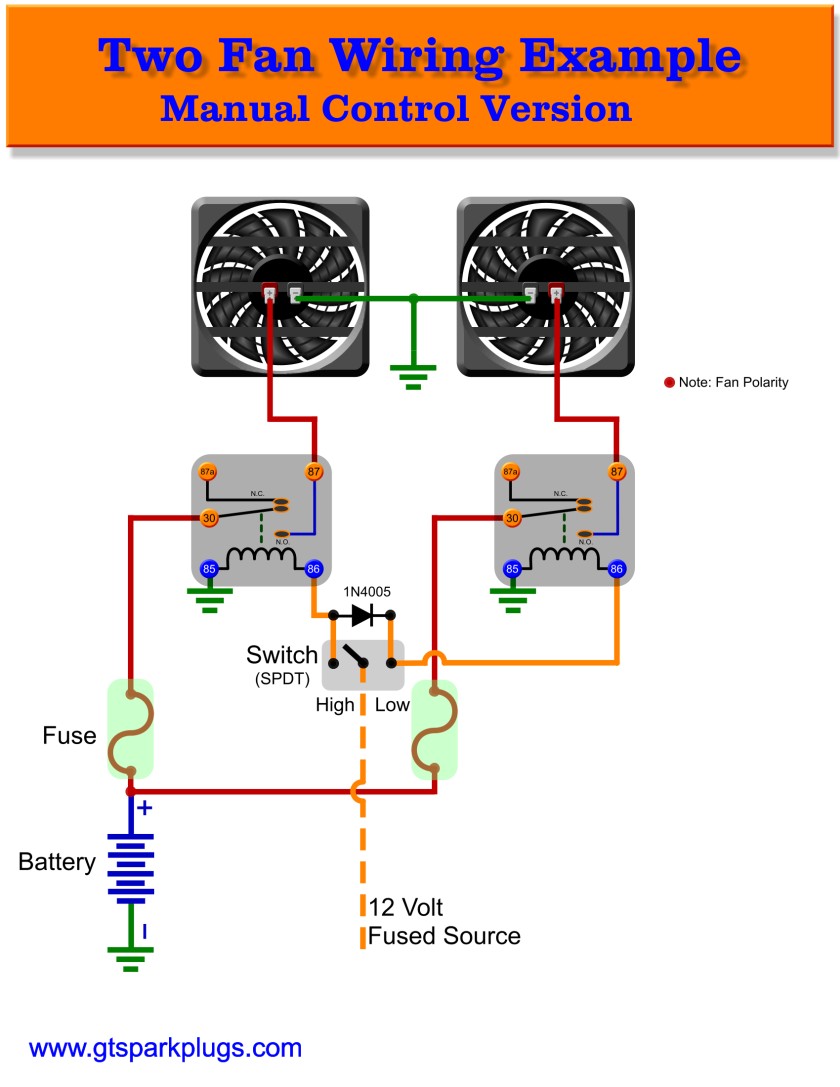
Well, if you see what's going on you will say it's not really two speeds at all, but really two levels one fan or two fans on full speed. You are correct, but I'm not sure anyone would get the "2 Level Speed Control" idea.

In any case, this is a bit more complex circuit, well only a little. The idea in this case is a toggle switch that can control if No fan, one fan or two fans are operating. This is done with 2 relays of appropriate amp rating. The small triangle looking thing over the switch is a DIODE. This prevents the current to flow in one direction and allows it in the other. The part cost about 25 Cents (1N4001 - 1N4007 parts could be used). With some changes this circuit could switch the ground side of the circuit instead of the 12 Volt Fused Source side (ask if you need this I can make it up and post)

Operations


If you had a SPDT Center Off switch, it has 3 positions, Left, Center, and Right. In the Center position no contact would be made to either side and both fans would be OFF. If you complete the circuit to the LOW relay side only the right hand fan will go ON. If you connnect to the HIGH side of the switch BOTH relays will be actuated and both fans will be ON.
Two Speed Manual Automotive Fan Control
Automotive Fan Relays

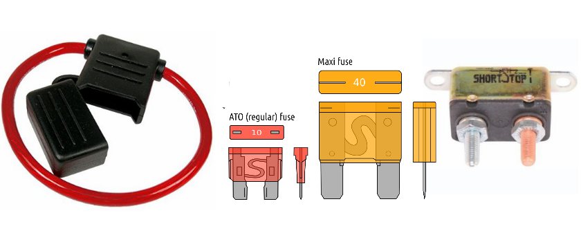
Common Automotive Fan Fuses


Above - Some fan fuse solutions. You have a few options when doing fuses or circuit breakers. The only options
that is not allowed is to not use one!

Left Most - This is an inline Maxi-Fuse harness. These are recommended! Nice thick wire and waterproof case
make these a nice low cost inline fuse holder. Maxi-Fuses can be had from 20-100 Amp in rating, perfect for your
fan installation.

Center - The typical automotive ATO / ATC style fuse next to the Maxi-fuse. The ATO style can be used (with
appropriate inline holder) for lower amp fuses. As you might guess I prefer the Maxi-Fuse. It's available in different
ratings most are prefect for high current electric fans.

Maxi-Fuse Color Ratings


Yellow - 20 Amp
Green - 30 Amp
Orange - 40 Amp
Red - 50 Amp
Blue - 60 Amp
Brown - 70 Amp
Clear - 80 Amp
Purple - 100 Amp


Right Most - This is a reasonable option, the automatic reset circuit breaker. I'm not so keen on the automatic
part, but if you have a short then fix the issue you are back on your way without replacing anything. The downside is
these will cycle on and off (slow delay) until the problem is fixed. These are available in many different current
ratings.


Fuse Current Ratings


If the fan is rated at 10 amps, typically that is the running current. At start up fans can draw more amps by a good
margin. For most fans you will want to start with a 20 Amp Fuse. This will work with fans in the 10-12 Amp range
and keeps things safe. Typically a good starting point beyond that is 50% more amps in the fuse then round up to
next size.

For example if you are using an 18 Amp fan, add 9 Amps (that's 50% more) which gives 27 Amps. Their is no 27
Amp fuse so round up to 30 Amp. If running multiple fans it's often better to individually fuse them, if one shorts out
you at least have a second still working. When in doubt look at the manufactures site the typically give some
information on fuse size.

Wire Capacity


While talking about fuses it's also important to ensure you use a thick enough wire for your high power connection
to the fan. Relays take very little current, but the fan is a hog. Use the Wire Size Calculator to get you a rough size.
In all cases I would not go smaller then 14 Gauge for the smallest of fans. With wire, bigger, well thicker is better.
Electric Fan Fuses

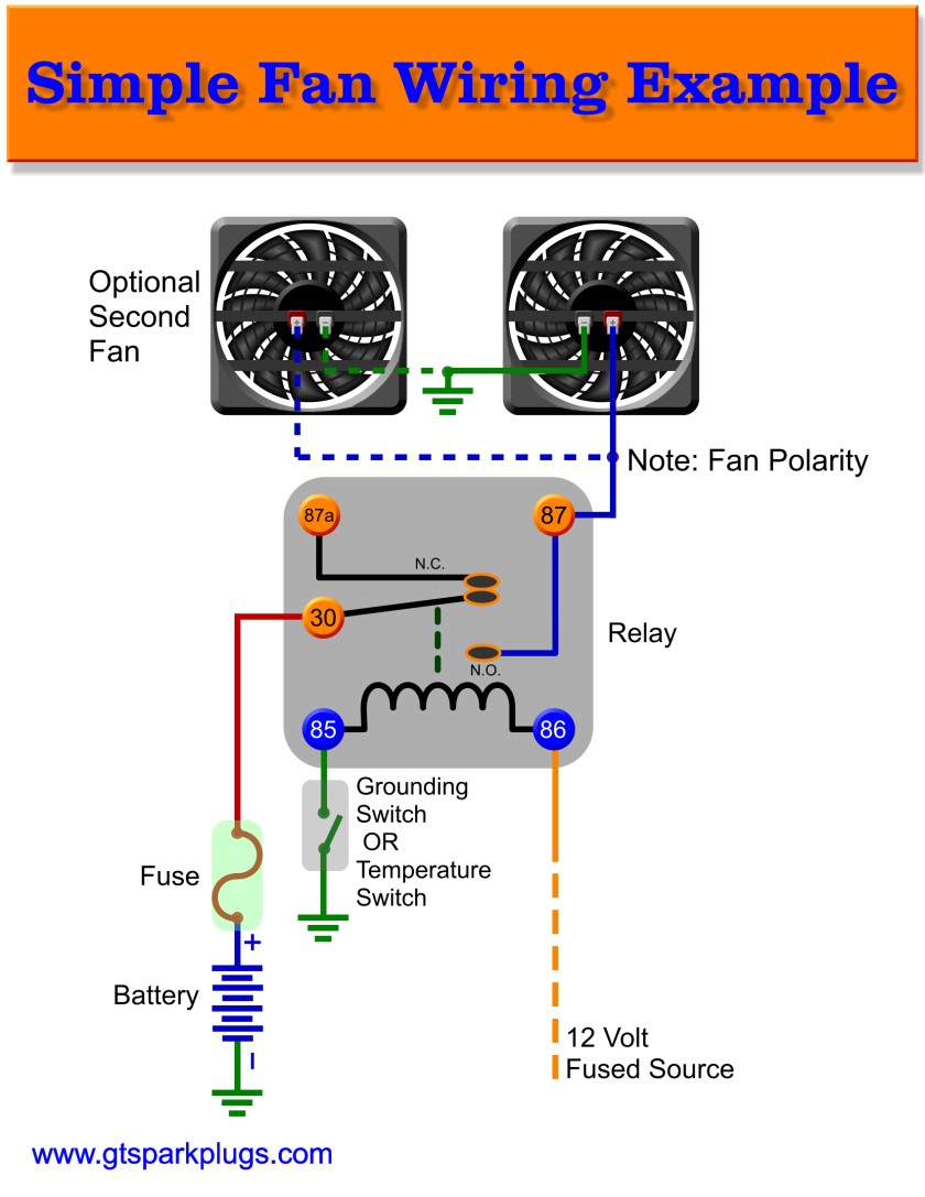
Simple Fan Relay Wiring


The above image is a very simple and basic fan wiring diagram. It can support one or two fans and uses a simple relay circuit to turn them on. The switch can manually turn the fans on or off. If you use a temperature switch, that can be used to turn them on when the engine reaches some set temperature. Often, but not always these temperature switches are single terminal with the body going to the engine block or radiator, both typically are grounded in older cars. In some newer cars you may be 2 terminal temperature switches, in this case one side would go to the relay, the other would go to ground.

The "12 Volt Fused Source" wire would go to something like the ignition switch that would give it power when the key is on. In some cars it's wired to an always on source (still fused) so the car can cool down even after the key is off. Just be sure that you know the short coming in that scenario and that in odd conditions you could end up with a dead battery. Some cars have time delays that eliminate the possiblity.

Automatic 2 Speed Fan Control


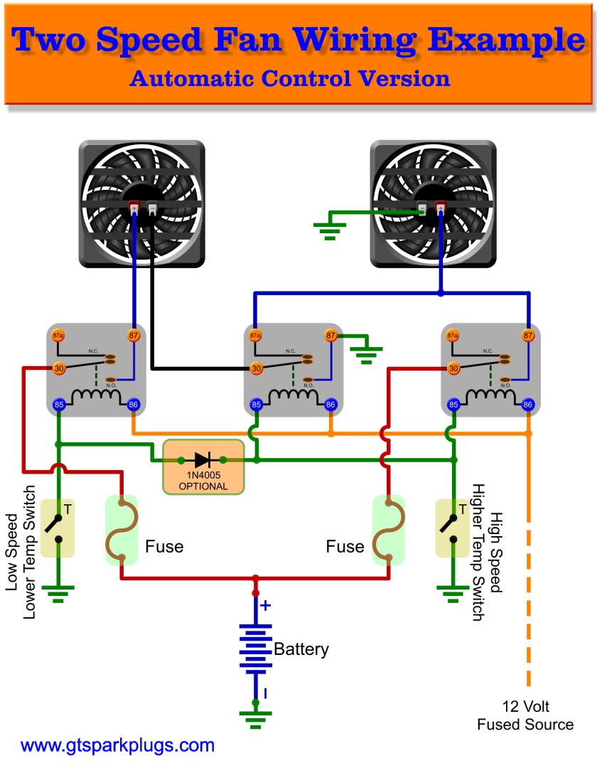
OK here is a true 2 speed fan control. This wiring diagram uses three relays. Each should have the capacity of a single fan.

Fan Speed Control


The idea here is that fans are 12 Volt motors, and typically will work at reduced capacity at a lower voltage. Lets say we put both fans in series. That would make the effective voltage to each fan at 6 Volts, 1/2 of the required voltage. In that case the fan will spin slower.

If we want full speed then we need to re-connect the wires so that each fan will receive the full voltage. With some simple relay wiring we can do this pretty easily.

The LOW speed temperature switch needs to be set at a lower temperature value the the high speed or this really doesn't work. Given that the lower temperature switch turns on first and the higher temperature switch later makes this all work like a charm.

As previous wiring diagram we use a DIODE, but in a slightly different way. You can omit the diode, but if your low temperature switch fails, you will ONLY have one fan on (the High Side on the right). We can make this circuit much better by using the DIODE to also ensure if the HIGH temperature fan is on the LOW temperature fan comes on as well. The circuit will still allow the 2 speeds but ensures that a bad low temperature switch will not keep both fans blowing if it overheats.

This is yet a more complex circuit then the previous but still within reach, yet provides more functionality if you need it.

Operations


If none of the temperature senders are triggered both fans are off. If the LOW Temperature side is triggered BOTH fans will come on at roughly half speed. If the HIGH Temperature switch comes on both fans will switch to full speed mode. If you do not have the OPTIONAL DIODE this will only be true if the LOW Temperature switch is also on. Add the DIODE it's about 25 Cents and adds some redundancy to the system.


MORE TO COME, TIME FOR SOME SLEEP :) IF YOU HAVE QUESTIOINS CLICK THE SPARK PLUG IN THE TOP UPPER RIGHT OF THE PAGE
AutomaticTwo Speed Automotive Fan Control
GTSparkplugs Header
Click for Contact Page Click for Contact Page